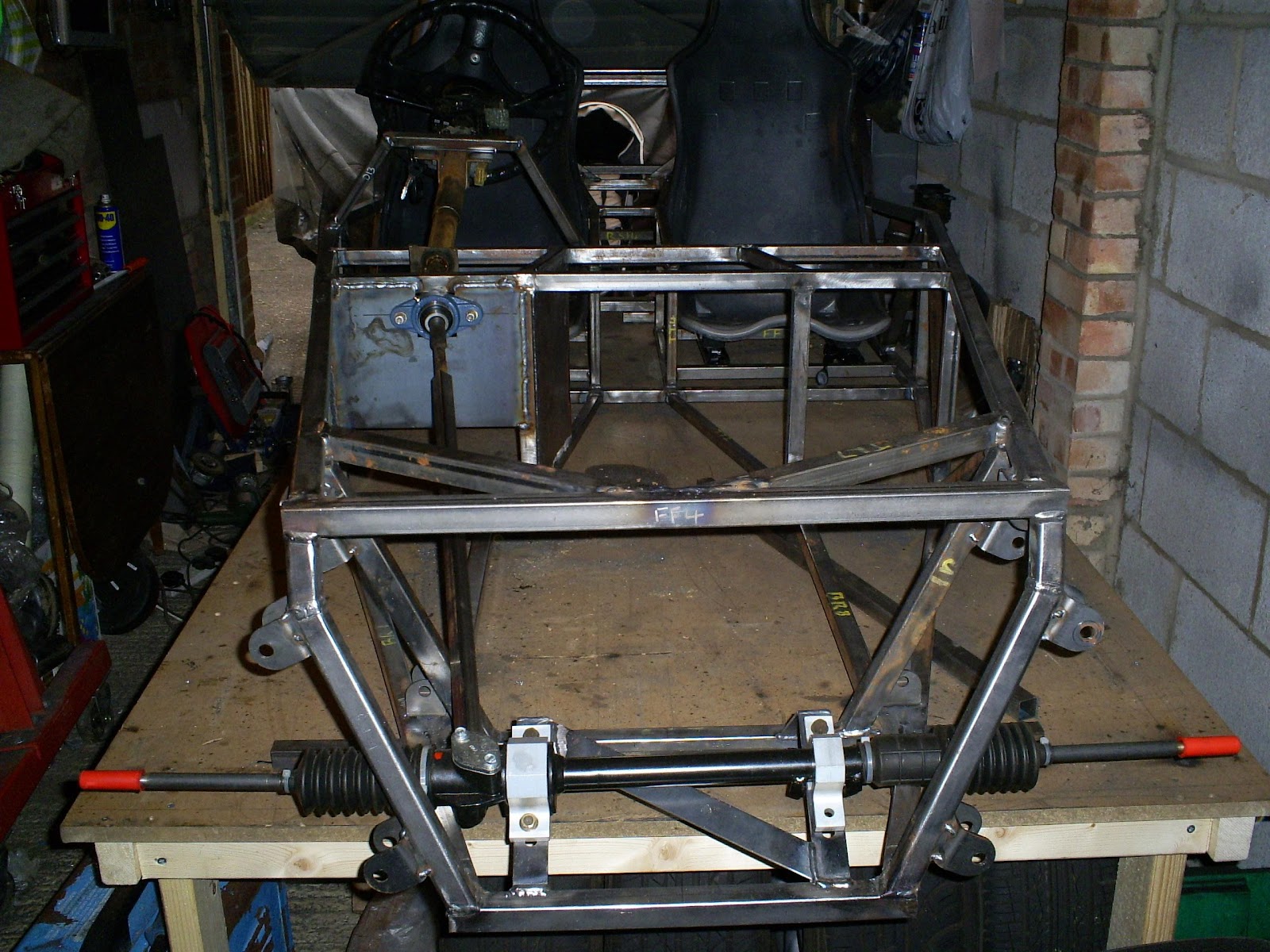
I've been suffering from a severe case of the man-flu for the past week so haven't done much on the build...
I managed to brave a few hours in the garage today though and have (possibly) finalised my steering design.
After lots of playing around I've decided to keep it much the same as my first attempt, but have managed to drop the height of the steering wheel by an inch or so. Ideally I would have liked it another inch or so lower (and possibly a couple of inches futher forward) but I can't easily acheive that without cutting a big hole in TR9, or making the steering linkages go through a rather tortuous path.
So basically all I've done is get rid of the gap I had previously left between TR9 and the column, so the column just touches it.
I did that by cutting off the top rail of the column support SW2 and replacing it with another tube a little lower.
I guess I could have just added a spacer, but it wasn't level anyway which would have forever bugged me if I had left it as it was!
Whilst I was at it I also added a little plate to TR9 with two holes in it so I can use a 38mm exhaust clamp to add a little more support for the column:
I've been wondering for a while how to link the mazda column to the escort rack and had a bit of a brainwave this weekend. It's possibly a silly idea, and a waste of a perfectly good sierra column, but...
I started off with the MX5 steering rack linkage, which I cut down on one end:
I then dug out a Sierra colmn I had lying around, chopped it in half and mated the two together:
The Mazda end mates with the lower part of the MX5 column, and the Ford end mates with the steering rack using one of RallyDesign's Sierra-to-escort linkages:
Saturday, 30 July 2011
Sunday, 24 July 2011
Gearbox Mount
After quite some time pondering how to mount the gearbox to the chassis, this is what I came up with.
I'm not sure I'm altogether happy with it, but I can't think of a better way...
I started off tacking a 3mm plate into the base of the tranny tunnel, with an engine mount from a classic/original mini bolted to it:
At the rear of the gearbox are two threaded bolt holes (M10 I think). I bolted a 3mm plate to these, and another 3mm plate to the mini mount, then with the gearbox supported where I wanted it, I tacked a couple of bits of 3mm plate into the gap.
I then unbolted it, added some sides, and fully welded it:
Here it is back in the chassis:
I'm not sure I'm altogether happy with it, but I can't think of a better way...
I started off tacking a 3mm plate into the base of the tranny tunnel, with an engine mount from a classic/original mini bolted to it:
At the rear of the gearbox are two threaded bolt holes (M10 I think). I bolted a 3mm plate to these, and another 3mm plate to the mini mount, then with the gearbox supported where I wanted it, I tacked a couple of bits of 3mm plate into the gap.
I then unbolted it, added some sides, and fully welded it:
Here it is back in the chassis:
Wednesday, 20 July 2011
Handbrake Lever
I spent the last couple of garage sessions figuring out how to mount the handbrake lever.
The choice of position was fairly limited. It had to go in the tranny tunnel, and couldn't go on the drivers side because the propshaft is offset towards that side which doesn't leave enough clearance. So passenger side it was.
I decided to add a triangular plate to existing chassis members to support the rear of the lever.
For the front of the lever I added a new length of 19mm box section to the tunnel, then welded a small plate to it.
The lever is mounted to the two plates using M8 bolts and spacer tubes.
At the moment I have the bolts coming in from the passenger side, this won't be possible once the tunnel sides are in place.
Because access is going to be limited I plan to weld nuts onto the plates to make assembly easier.
I still need to figure out what to do with the handbrake cable itself, but that's a job for another day.
The choice of position was fairly limited. It had to go in the tranny tunnel, and couldn't go on the drivers side because the propshaft is offset towards that side which doesn't leave enough clearance. So passenger side it was.
I decided to add a triangular plate to existing chassis members to support the rear of the lever.
For the front of the lever I added a new length of 19mm box section to the tunnel, then welded a small plate to it.
The lever is mounted to the two plates using M8 bolts and spacer tubes.
At the moment I have the bolts coming in from the passenger side, this won't be possible once the tunnel sides are in place.
Because access is going to be limited I plan to weld nuts onto the plates to make assembly easier.
I still need to figure out what to do with the handbrake cable itself, but that's a job for another day.
Up to Date!
If you've read from the first post, my blog has now just about caught up with where I am in reality. Hurrah!
Hopefully that might mean my posts from now on will be roughly in real time and might even be a bit more accurate and detailed as I won't have to rely on my rather poor memory of what happened and in what order many weeks ago!
Engine Mounts
Whilst I had the engine temporarily in the chassis I decided to fabricate the engine mounts.
On the advice of Saturn Sports Cars I decided to position the engine with the bottom of the sump 40mm below the bottom of the chassis.
Ideally you would want the sump level, but the MX5 engine is quite tall and wouldn't fit under the bodywork if this were done.
With the engine resting on the table I raised the chassis 40mm above it, and positioned the engine centrally within it.
To make it easier to line up, I also temporarily fitted the diff and cut down the propshaft.
I then set about making the mounts. These were constructed with 3mm steel plates and strip.
The rubber mounts are from a landrover.
Obviously they need fully welding, but that can wait for a later date. Once I've done that I'll add a top plate to them, leaving a gap to access the rubber mounting nut. I'll also trim down and shape the plates to make them look a bit nicer.
With the engine positioned centrally the gearstick and propshaft sit slightly to the drivers side, which makes sense as the diff is offset that way too.
On the advice of Saturn Sports Cars I decided to position the engine with the bottom of the sump 40mm below the bottom of the chassis.
Ideally you would want the sump level, but the MX5 engine is quite tall and wouldn't fit under the bodywork if this were done.
With the engine resting on the table I raised the chassis 40mm above it, and positioned the engine centrally within it.
To make it easier to line up, I also temporarily fitted the diff and cut down the propshaft.
I then set about making the mounts. These were constructed with 3mm steel plates and strip.
The rubber mounts are from a landrover.
Obviously they need fully welding, but that can wait for a later date. Once I've done that I'll add a top plate to them, leaving a gap to access the rubber mounting nut. I'll also trim down and shape the plates to make them look a bit nicer.
With the engine positioned centrally the gearstick and propshaft sit slightly to the drivers side, which makes sense as the diff is offset that way too.
Engine Test Fit
7th July 2011
After playing about with the steering column I decided I needed to get the engine in the chassis to check for clearance.
Because I have limited head room in my garage I decided to get the engine in the chassis in a bit of a roundabout way...
Firstly I lifted the chassis off the build table and removed it from the garage. In it's current state I could just about lift it by myself.
Next I used the engine crane to get the engine onto the build table.
My plan was that I could then simply drop the chassis over the top of the engine.
It wasn't quite as easy as that as it happened, an hour or so of swearing, sweating, grunting, and removing bits from the engine later I had managed it:
After playing about with the steering column I decided I needed to get the engine in the chassis to check for clearance.
Because I have limited head room in my garage I decided to get the engine in the chassis in a bit of a roundabout way...
Firstly I lifted the chassis off the build table and removed it from the garage. In it's current state I could just about lift it by myself.
Next I used the engine crane to get the engine onto the build table.
My plan was that I could then simply drop the chassis over the top of the engine.
It wasn't quite as easy as that as it happened, an hour or so of swearing, sweating, grunting, and removing bits from the engine later I had managed it:
Steering Column, first attempt
5th July(ish) I made my first attempt at mounting the steering column.
I used the standard steering column support rails (SW1-3), and mounted them in roughly the standard position. I did however trim them so the top sat slightly lower.
I did away with the two angled strips from the book as they were no use for the MX5 steering column and replaced them with a small plate with two holes in to bolt the column to.
At the bulkhead, the footwell panel is book spec, but without the three plates that make up the bush support - these were replaced with a bearing (UCFL205-14 22mm).
Initially I left a gap of about 5mm between the column and BR9 (or is it 10?). Because the MX5 column is much chunkier than the Ford one, this left the steering wheel rather too high.
The steering rack in the photos is a brand new semi-quick rack for a Mk2 Escort.
It is usually available in quick (2.4 ratio), and semi-quick (2.9 ratio). Initially I wanted a 2.4, however I managed to pick up this one fairly cheap from a failed build.
The rack mounts are solid aluminium ones I bought from ebay.
The reason the Mk2 Escort rack is used is that the MX5 one is too wide, and also powered, which is not required and involves far more work and weight. The chassis is designed around the escort rack so it makes sense to use it.
As I'm not happy with the height of the wheel I plan to rework it in the near future. I had a couple of ideas, but needed to check for clearance through the engine bay, which leads me onto my next post, and a bit of a diversion...
I used the standard steering column support rails (SW1-3), and mounted them in roughly the standard position. I did however trim them so the top sat slightly lower.
I did away with the two angled strips from the book as they were no use for the MX5 steering column and replaced them with a small plate with two holes in to bolt the column to.
At the bulkhead, the footwell panel is book spec, but without the three plates that make up the bush support - these were replaced with a bearing (UCFL205-14 22mm).
Initially I left a gap of about 5mm between the column and BR9 (or is it 10?). Because the MX5 column is much chunkier than the Ford one, this left the steering wheel rather too high.
The steering rack in the photos is a brand new semi-quick rack for a Mk2 Escort.
It is usually available in quick (2.4 ratio), and semi-quick (2.9 ratio). Initially I wanted a 2.4, however I managed to pick up this one fairly cheap from a failed build.
The rack mounts are solid aluminium ones I bought from ebay.
The reason the Mk2 Escort rack is used is that the MX5 one is too wide, and also powered, which is not required and involves far more work and weight. The chassis is designed around the escort rack so it makes sense to use it.
As I'm not happy with the height of the wheel I plan to rework it in the near future. I had a couple of ideas, but needed to check for clearance through the engine bay, which leads me onto my next post, and a bit of a diversion...
Subscribe to:
Posts (Atom)