Here's a couple of pics of the pedal box wiring:
Again, I junked this part of the MX5 loom and made a new one, and again it ends up behind the scuttle.
Monday, 14 May 2012
Wiring - Tunnel Loom
Here's some pics of the loom running down the tranny tunnel:
I junked the original tunnel loom and made this one from scratch.
It's covered in heat-shrink to protect it, and clipped into place with nylon p-clips and pop rivets.
At the rear it goes to the lights, fuel pump, and fuel sender (or will do when I wire the rear end up!).
In the tunnel it goes to the handbrake and gearbox (reverse/neutral/speed).
The front end of it goes up into the scuttle where eventually all the wiring will come together.
I junked the original tunnel loom and made this one from scratch.
It's covered in heat-shrink to protect it, and clipped into place with nylon p-clips and pop rivets.
At the rear it goes to the lights, fuel pump, and fuel sender (or will do when I wire the rear end up!).
In the tunnel it goes to the handbrake and gearbox (reverse/neutral/speed).
The front end of it goes up into the scuttle where eventually all the wiring will come together.
Clutch Switch
As the MX5 ECU needs a clutch switch I had to find a way to add one.
The OEM switch is an electrical one driven directly by he clutch pedal. Because the pedals in the roadster are 'upside down', the only way I could realistically use the OEM switch would be to have it bolting into the floor from underneath the car.
As that would last the length of the trip to my first speed bump I needed a different approach...
So I decided to use the same pressure switch I used for the brakes and stick it the clutch line using another 3-way T-piece:
As an added bonus it put my flexi-line to the clutch slave in a better place.
There is some debate as to whether there will be enough pressure in the line to switch it, but time will tell!
The OEM switch is an electrical one driven directly by he clutch pedal. Because the pedals in the roadster are 'upside down', the only way I could realistically use the OEM switch would be to have it bolting into the floor from underneath the car.
As that would last the length of the trip to my first speed bump I needed a different approach...
So I decided to use the same pressure switch I used for the brakes and stick it the clutch line using another 3-way T-piece:
As an added bonus it put my flexi-line to the clutch slave in a better place.
There is some debate as to whether there will be enough pressure in the line to switch it, but time will tell!
Wednesday, 18 April 2012
Brake Lines
Managed to finish off my brake lines over the last few days.
I've used 3/16" copper lines, and (mostly) M10x1 fittings.
The MX5 master cylinder is quite nice as it has 3 outputs - 2 for the front lines and one for the rear.
I've stuck a T-piece in the rear line to attach a Mk1 VW Polo brake switch for the brake light.
Following that in the rear line is a Mondeo reduction valve to reduce bias to the rear (Ford Part# 1113275).
----
UPDATE: I had to remove the bias valve to get through IVA. With the valve in place the rear brakes were doing bugger all and I failed on overall braking efficiency.
----
At the end of the tunnel is another T-piece to split the rear line to the rear calipers.
I got the front flexi lines from Furore. Was very impressed with their service, they were custom made and arrived next day!
Specs were:
400mm long, M10x1 female swivel with 15 degree bend one end, and 10mm banjo the other.
Probably ordered them slightly too long if I'm honest, but hopefully that won't cause me any problems.
For the rear flexis I'm going to use the MX5 ones for now as they fit nicely and I'm feeling a bit poor at the moment.
I've used male-male bulkhead fittings from motorsport-tools.com (part MSTRD1541) for the transition between copper and flexi lines.
I've used 3/16" copper lines, and (mostly) M10x1 fittings.
The MX5 master cylinder is quite nice as it has 3 outputs - 2 for the front lines and one for the rear.
I've stuck a T-piece in the rear line to attach a Mk1 VW Polo brake switch for the brake light.
Following that in the rear line is a Mondeo reduction valve to reduce bias to the rear (Ford Part# 1113275).
----
UPDATE: I had to remove the bias valve to get through IVA. With the valve in place the rear brakes were doing bugger all and I failed on overall braking efficiency.
----
At the end of the tunnel is another T-piece to split the rear line to the rear calipers.
I got the front flexi lines from Furore. Was very impressed with their service, they were custom made and arrived next day!
Specs were:
400mm long, M10x1 female swivel with 15 degree bend one end, and 10mm banjo the other.
Probably ordered them slightly too long if I'm honest, but hopefully that won't cause me any problems.
For the rear flexis I'm going to use the MX5 ones for now as they fit nicely and I'm feeling a bit poor at the moment.
I've used male-male bulkhead fittings from motorsport-tools.com (part MSTRD1541) for the transition between copper and flexi lines.
Saturday, 14 April 2012
(Lack Of) Progress Update
Haven't updated for over a month, the reason being I've moved house.
Just about settled in the new place now though, and starting to find time to work on the car again.
Nothing to report yet, but here's some pics of the roadster when we dragged it out of the garage to move it to its new home:
Just about settled in the new place now though, and starting to find time to work on the car again.
Nothing to report yet, but here's some pics of the roadster when we dragged it out of the garage to move it to its new home:
Tuesday, 6 March 2012
Handbrake cable routing
Here's a quick pic of my handbrake cable routing.
I bolted the handbrake cables to the big diff mount washers which hold them in place and stop them fouling on anything.
Front Diff Mount
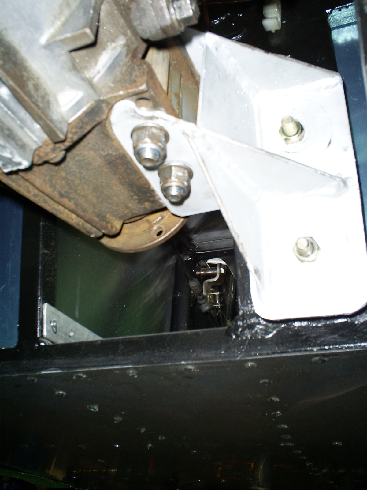
I finished my front diff mount off last week and fitted it yesterday.
I forgot to take any pics of it before I bolted it on, but here it is in place. It's in a bit of an awkward position to take photos of, but you probably get the idea:
I fabricated it out of 3mm steel plate, and it's bolted via a pair of landrover engine mounts to a 6mm plate welded into the chassis seat back.
I'm not particularly keen on using the rubber mounts in shear, but I think (hope!) they'll be ok.
The mount is attached to the front of the diff using a pair of 110mm M12 bolts.
The bolt holes in the diff are sleeved down using some ally tube to get a better fit on the bolts.
------------------
EDIT:
This was another bad idea on my part!
After 650 miles of driving the landrover mounts sheared off resulting in a broken diff and damaged propshaft...
------------------
I forgot to take any pics of it before I bolted it on, but here it is in place. It's in a bit of an awkward position to take photos of, but you probably get the idea:
I fabricated it out of 3mm steel plate, and it's bolted via a pair of landrover engine mounts to a 6mm plate welded into the chassis seat back.
I'm not particularly keen on using the rubber mounts in shear, but I think (hope!) they'll be ok.
The mount is attached to the front of the diff using a pair of 110mm M12 bolts.
The bolt holes in the diff are sleeved down using some ally tube to get a better fit on the bolts.
------------------
EDIT:
This was another bad idea on my part!
After 650 miles of driving the landrover mounts sheared off resulting in a broken diff and damaged propshaft...
------------------
Subscribe to:
Posts (Atom)